In 2022 I made one 200m long beverage antenna for our IOTA (S21DX, 2022) which was around 2m high from ground. For some reason (most probably very high conductive wet soils in the island) the antenna was a disappointment for lower band. We end up using the vertical transmit antenna for receive as well. As 160m was not a priority for us for an IOTA, it took us few days to complete the antennas for 160m, we managed to do around 280 FT8 QSO at the last day of our IOTA.
As the beverage was a failure, I started looking for another solution and came up with the K9AY loop, which is not too critical to build, and the concept is straight forward. Idea of making the K9AY four directional is abundant in the internet, using two relays to change the loops wires.
Pre-Amps: Next I started looking for a pre-amp and chose the popular Norton design. Later added provision for a 160-80m Bandpass filter as well. Both the Pre-Amp and BPF can be turned on/off using small signal relays, activated by small toggle switches at the RF unit, or from the shack from the controller.
Another three relays are used to do a combination of termination resistor chaises. Selection of the resistor can be done using three toggle switch at the RF Unit or remotely from the controller using a 8 position/gang switch.
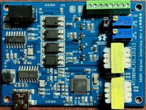
Control signal between the RF Unit and Controller can be done using cheap CAT5 wires (we need all the 8 wires). A small 12v transformer can be used inside the controller or 12V can be feed from the main shack power (DC). Please make sure the supply DC is clean, or the preamp may get additional noise and interference.

Surge Protection: in total three GDT (Gas discharge tube) has been used. The first two are at both end of the active loop, and the third one is at the controller. Chose a small V value GDT as it is a receive only antenna. 70V GDT you can get a bunch with few dollars. This might save your expensive rigs from static and surge.
TX Protection: I have also added a PTT relay for upstream external devices which has a limited receive front end overload protection as well. When radio pulled the PTT down, relay U8 will remove the antenna connection from the radio and ground the RX input. Same time another transistor will be pulled down (open collector), this connection can be used as a PTT for other external devices, such as a SSPA. The RX-input has two sets of 4 series Schottky diode. This should clip the signals to 1.28V if its overloaded.
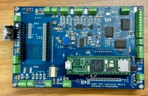
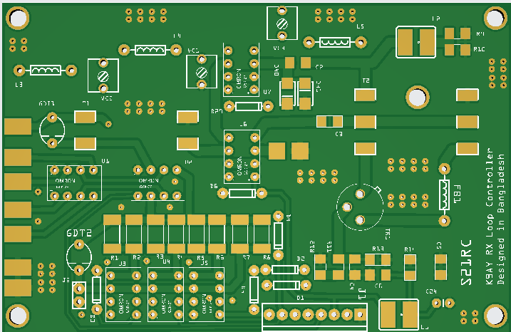
PCB: the PCB is 100x100mm to get the special offer of some specific PCB manufacturer. Both the controller and RF unit PCB are designed together as a single board, there is no ‘v’ cut or slots to separate these two PCB (Manufacturer charges more for that), you need to manually cut the boards.
DOWNLOAD PCB GERBER
[Gary K9AY kindly gave permission to share my work which is based on his antenna design. The preamp part is a widely available Norton pre-amp. The band pass filter is designed using Elsie]
BOM: DOWNLOAD
Schematic:
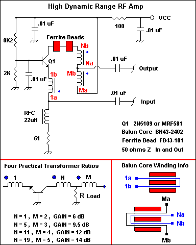
BPF: The bandpass filter is designed in elsie,, Shunt-input Chebyshev, Ripple Fc 2MHz, Center Fo 2.5MHz abd Passband ripple 0.01, as a receive antenna it should be very flexible, capacitor do not need to be exact but as near as possible. You can use multiple parallel MLCC NP0/C0G to achieve the values, parallel trimmer capacitor option is there – but only needed for fine tuning. If you want to use the antenna on higher band (60m and above) you can turn of the BPF from the shack control box. at higher band you may not need the pre-amp as well, you can turn the pre-amp off if needed as well from the shack. NB: You might make the system without the BPF, in that case just short the relay points (U7, middle pins with NOs) to bypass the BPF and do not mount Relay U7.

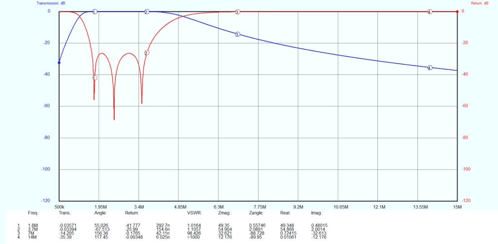
** Please make at your own risk, this is my first attempt to this antenna, and many small tuning of parts value might be needed. We will test the antenna in few weeks after getting the PCB from abroad.
