[PCB, Schematic, and microcontroller codes released under MIT license by S21RC. You are free to use the material for personal/commercial use as it is or modify if needed as per the condition stated in the license], in simple term, software should contain the same copyright/license file and attribution. HMI display should have the “info” screen with all information and the Splash screen.
UPDATE: 28 March 2024
PCB 3.0.2B – all known missing ground fixed.
The project is now tested and in usable state.
All files are in Github: https://github.com/s21rc/SSPA-Controller-rev3
UPDATE: 22 JAN 2024
PCB REV 3.0.2 fixed missing ground and 2 short on i2c line.
CODE: (in progress.)
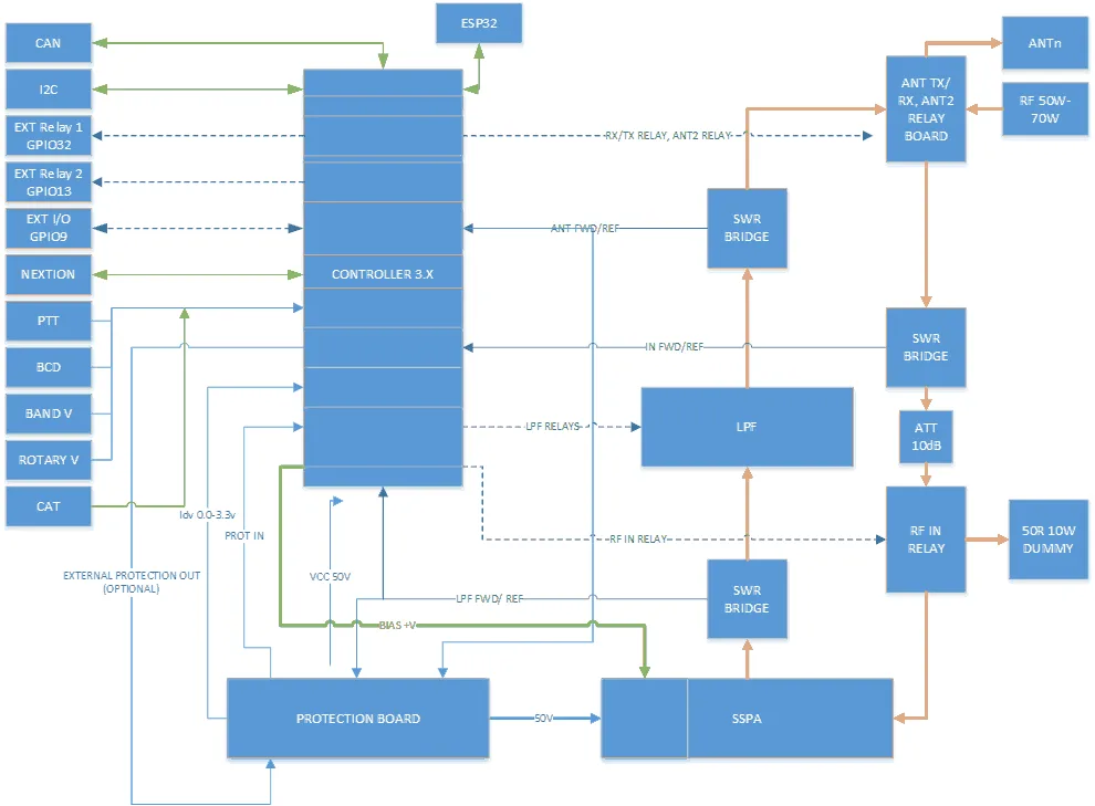
Function Block:
UPDATE 5 July 2023:
Rev3.0.1 BOM, CPL and Gerber uploaded.
UPDATE: During the test found some error and some improvement areas. New layout in progress.
Changes made:
1. CAT (CI-V) function added.
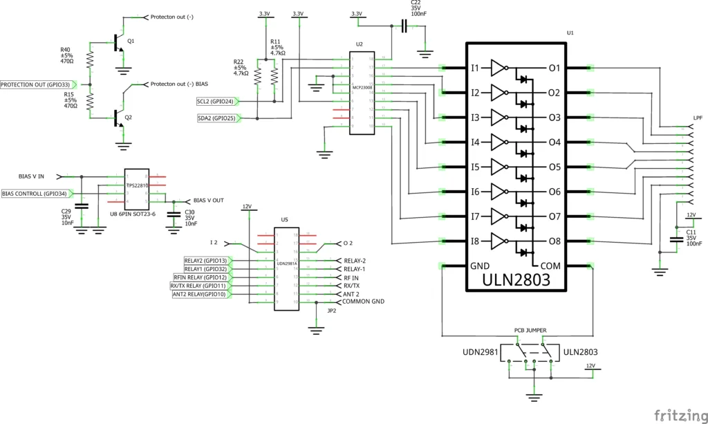
2. Pullup resistors added (error found during test – PCF8574 unable to drive ULN2803 without pullup)
3. External protection trigger IN is now routed through optocoupler.
4. BTS4141N replaced with TPS22810
5.
TEST RESULT:
1. Display function works ok
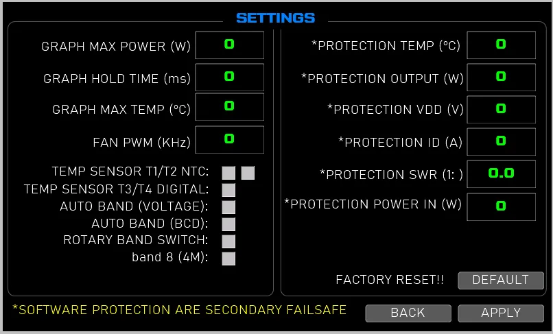
2. Setting save works ok.
3. Hardware protection for high input and swr tested ok.
4. Software protection works ok,
5. all temp sensor works ok.
6. Relay driver: Failed, need pullup resistors.
7. BIAS control Failed – BTS4141n might be fake.
8. All interrupt works ok.
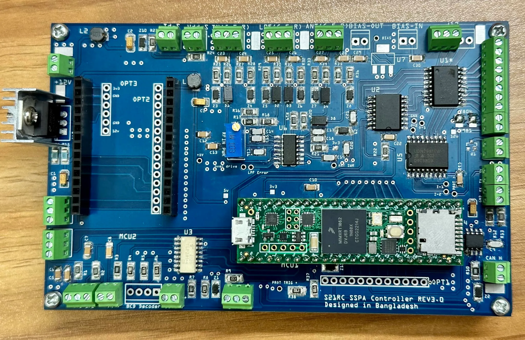
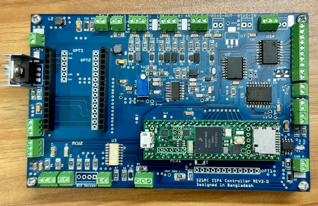
After making the basic controller v1 which only had few peripherals and used through hole components and cheap Arduino Nano I decided to make another version with more options and future expandability. The Controller Rev2.0 was designed with Arduino Mega for the higher count of I/Os, but that never left the design table as I was hungry for more speed/power and expandability options. Born the Rev 3.0 utilizing Teensy 4.1 Microcontroller board which runs at a huge 600MHz speed (NXP iMXRT1062 chip with ARM Cortex M7 core).
Except the headers and few parts, all other components are SMD to save space. 1206 packages (cap, res, diode etc) has been used for easy home soldering.
Features:
1. 600MHz MCU
2. Highspeed comparator (LMV339) for monitoring high SWR/Power
3. Same PCB can be used for both high side switch and low side switch LPF boards (The final IC need to be selected as per your LPF type)
4. WiFi application with a ESP32 Wroom module (Optional)
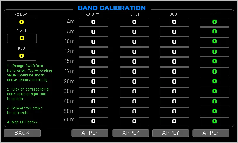
5. Band Decoder (BCD and Voltage)
6. PTT input, PTT relay control.
7. 8 LPF channel for supporting future 4m.
8. Voltage and Current monitor.
9. Rotary band switch (optional)
10. Onboard CAN Bus controller for common PSU
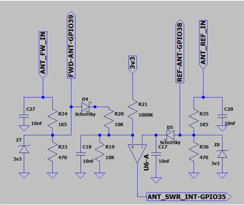
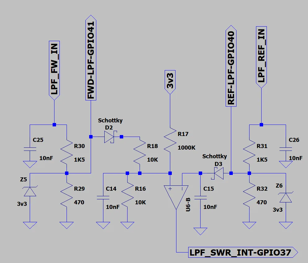
11. 3 directional bridge/ SWR bridge input (Amp in, Amp out, LPF out)
12. Digital and 2nos NTC Temperature sensor options.
13. Protection Trigger out for external protection board
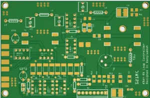
14. Board size (134x84mm) is same as Nextion 5″ display and can sit behind the display.
15. 2 25/31 KHz PWM out for Cooling fan.
16. OPT1 header has I2C, SPI and few I/O which can be used for more functionality or for a future daughter card (how about a 4×4 antenna switcher, or a sequencer, or….).
17. Can be used with 5/7/10 inch Nextion HMI display.
Software:
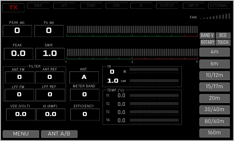
The display UI will be based on previous V2.0 UI with additional setup and features page for accommodating the new peripherals and options.
Or you can write your own code for this hardware.
Schematic:
Please check the Schematic folder in repo.
BOM:
BOM for Rev 3.0.1
PCB Gerber:
Download LDMOS SSPA Controller Rev3.0.1 (ZIP file contains the RS-274X Gerber files, and BOM & CPL files for the SMD components)
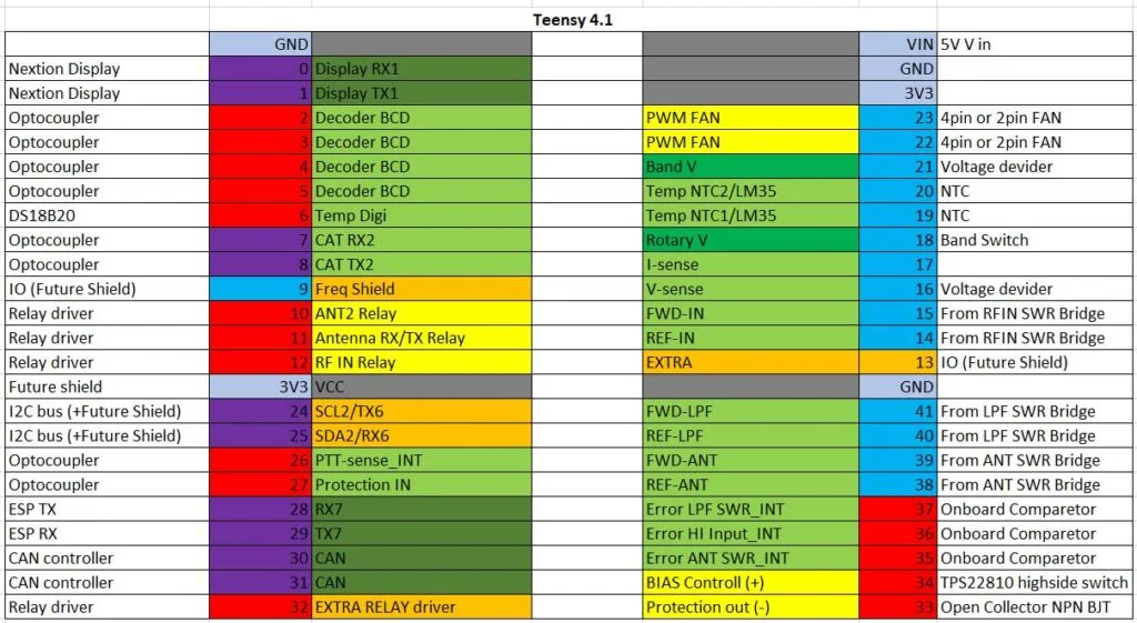
PIN Layout: Rev 3.0.1/2 Pinout
17 May 2023: Components are soldered. Still waiting for few parts to arrive, but I can start coding now [Rev 3.0].
KEEP THE BALL ROLLING:
Apart from countless hours (and lots of coffee) to design the circuit, testing, coding thousands of line etc (In addition to my full time work) – I also had to order every component from of-shore for my experiment. As I do not sell KIT – there is no return except my own happiness.
If you like my work and wish to use it – you may show your appreciation and support my effort by a small donation. This is completely optional and has no effect on the support I try to provide over email/chat/Github. 73, S21RC
[paypal-donation purpose=”” reference=””]


Hello, when will this version of the remote be available for testing? I have ordered a main control board from JLC.
Dear Rabby,
I have studied the design and features and would very much like to implement this into my current project, which is a little different from most:
I build a High Power 3 band 2m, 70cm, 23cm amp in one case, watercooled. This one doesn’t require band(filter) switching, but instead amplifier switching as each band carries its own Amp. Moreover, the power supply is programmable and can be read out over MODBUS. For TX/RX switching I use high power coaxial relays from Spinner (28V).
In how far is your code adaptable to make your design usable for this project?
Best regards and 73,
Mischa
Hi Mischa,
The code is written in very basic arduino style and is commented properly. you can easily modify it as per your need. The display is also you can edit with nextion editor to remove unnecessary button or to edit button location (drag and drop) or change label. Sure, you can use the 8 LPF our relay driver for other purpose as long you code it for that.
Thanks, 73, S21RC
Hi Rabby,
Great job! Thanks for hard work on the controller
Does the RIG (Band Voltage, BCD) feature works on the version 2 hardware.
I like the version 2 display very much.
HI Rabby,
This is great project. Thank you.
I have question, does v3 display HMI software maybe works with old HW (Arduino)? I can’t find Teensy4.1 to buy.
Best regards,
YU1ZP
Hello Zlatomir,
Sorry, v3 firmware will not work with v1.x PCB. You need the rev3 PCB.
Thanks, Rabby
Great job! I think about the same architecture of the controller. Do you have any PCB available?
Hi Vlad,
Sorry I do not have any PCB with me now. Also it is very difficult to post from my country, I am looking for a solution to sell kit/pcb. But at this moment not yet.
Thanks,
S21RC
What a great job, can only image the hours you put in. I’m in the process of planning my amp and require it to be remote.
I was hoping to piggy back on the teensy with my programming to interface with a raspberry pi. I can only find hex downloads, is there any chance of getting the sketch, even if beta?
Thanks
Hi Wayne,
My bad, should have provided the repo link. All PCB Gerber, Schematic, Display HMI and TFT, Teensy Hex and CPP are here: https://github.com/s21rc/SSPA-Controller-REV3
In addition, you might find this facebook group helpful where many others discuss regarding this controller:
https://www.facebook.com/groups/s21rc.controller
Regarding remote function, I have already started writing the codes, hopefully a beta release would be in 1 or 2 weeks time. Please check the facebook group to have a glimpse of the remote. The remote microcontroller ESP32 and Teensy would communicate over serial using JSON. The ESP will serve a webpage- so it would be platform independent and lightweight.
Hope you will like it.
Thanks, S21RC/Rabby
Where do you find the time. That is great news, I am in no rush, as I’m waiting on my amp kit. I looked at the facebook page and someone mentioned RF problems on the board. I build a mag loop controller many years ago and the designer used PCB chokes, not sure if you are aware or not. “The 2x 51 uH common mode chokes are used to squash any RF flowing back from the antenna through the stepper motor cable,
potentially locking up the microcontroller. The chokes also ensure that the controller does not radiate RFI into the antenna.
I really hate to wind toroid cores, so I use surface mount chokes, Digikey CMS1-8-R, specified at 2.2A”
Hi Rabby
I just finished upgrading my SSPA to liquid cooling and TFT screen using lite version. Works OK, but I needed to add some filtering (inductors, capacitors) at relay driver (using TD62783) as there was some problem with RFI.
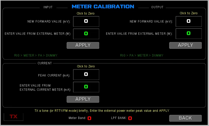
Just it is hard to properly adjust readings for REW RF power. Also I haven’t managed to work with 2 DS18B20 sensors (just 1 works, but I use 2 pallets). I adopetd the code to add STAND BUY / OPERATE BUTTON on the display, to take put QRO in stand buy mode when I wish. I’m not using rotating band select switch. I also changed the display bottons as my LPF has 3 bands on the same botton (the sam LPF for 20, 18 and 15m). I have some pictures on QRZ.COM.
I’m planing to upgrade on ver 3 as the Tennsy is much faster and to use BCD/CIV decoders for LPF switching.
Perhaps someone has finished the project with ver 3 and have some PCB avalable? I’m interested to buy PCB if awailable.
vy 73, Branko, S52V
Hello Branko,
I am unable to send you PCB due to export restriction in my country. Please check this Facebook group where other share/exchange ideas, extra pcb etc.
https://www.facebook.com/groups/s21rc.controller
Thanks,
73, s21rc
very interestting project, as i made myself simular project ( not this fancy looking) will consider my next build of new SSPA for 6m ( 50Mhz) to try this. nextion designed software looking fantastic !! If some1 did order too many boards and want to share teh cost with me please let me know.
cheers 73′
Jasper PA2J
Hello Jesper, thanks for comment. You can look into the “s21rc sspa controller” facebook group where people discuss and also swap extra pcb. Thanks, s21rc
Thanks for the Reply Fazlay ! do not have FaceBook 🙂
but will will find a way. I it possible to edit the Nextion part because want to leave out some parts and change colors…
wit the TFT now editting is not possible ( what i perfectly understand because of the hudge work it contains)
Thanks again
Hi Jesper, the editable HMI is also given, please check the display section in the github repo. You can use Nextion Editor to edit change display layout/content. 73, S21RC
Use a DC DC converter and set it to 7volt – the dissipation will reduce appreciably. Board ordered – Another week to arrive
Hello Rabby,
I just received 5 boards populated, begin testing… I put a 7805 1.5 amp… but still geting very hot. I may hav to add a separate regulator just to feed the Nextion. That ok anyway i will put the screen in a separete case, it will fit better on the desk away from the amplifier, 73
Hi Madhu,
V3.0.2(Gerber 3.0.2b) is usable and few OM making it already (update you can see in the facebook group). We are doing small software tuning and working on added features now (CAT over Bluetooth, remote monitoring over web etc).
Thanks, s21rc
Hai Fazlay,
Any new update of SSPA V3 PCB dovelopments ?
Regards,
Madhu.
Thanks
Hi Rabby,
Good to see the version3.0 all files are out in the repository. Thanks for hard and good work,
Unfortunately, the schematics is missing which is actually very important for me probably for others.
It will be nice if you can upload a pdf file in Monochrome that will help to get a good print out
Hello Probir ji,
The schematic is almost done (OM F8FQX is kind enough to draw it with kicad), doing final check for minor label correction. A draft version is already shared in the facebook group s21rc sspa controller. I will upload it in the repo once all the correction is done.
Dear Fazlay,
If I have to assemble with my own risk, how I get the PCB,circuit details and softwares
Regards,
Madhu.
Hello Madhu,
As the project is still in progress thats why the disclaimer has been added.
All codes (mcu code, display code), pcb gerber for fabrication house, CPL and BOM for PCBA service etc are in the github, github.com/s21rc
As these project used Surface Mount components- good soldering skill is needed.
I usually make the PCB from JLC PCB, China. Thanks, 73, s21rc
Thank you Fazlay for qick replay.
Which bom code for request pcb from JLC ? Or how can request a pcb?
Regards,
Madhu.
Hai
I am very intrested thos board. Fully asseble vertion available?
Regards,
Madhu
VU3MQK/A65DE.
Hello Madhu, I do not have the option to send PCB/Circuit abroad (Local post do not allow). Its a open source project and you have to make it your self. There are few OM sharing their PCB as they have extra – you will find the offers in facebook SSPA groups. I have got your email with suggestions – thanks. Will reply in detail later. 73, S21RC
Hope you are Back
Hello OM Probir, Yes I am back to Dhaka and resumed this project. New code uploaded – Basic functions working – now doing CIV implimentation.
Great you resumed your project …closely checking the status ONCE i see all working fine I will order the PCB Thanks
BTW, could you please provide me the part # of LCD Display
You can use any 5″, 7″ Nextion Display (800×480 pixel). My test version is a 5″ Nextion Enhanced (NX8048K050).
Great feedback. Yes, time to download the Gerber. To my wish list if the Power readout can be 2killowatt – that will be awesome
Yes, the new UI has enough space to show 4 digit.
who are you using to make the pcb
Hi OM, I use JLCPCB to make the PCB. Thanks, S21RC
Hi Rabby,
Just got involved in my MQTH work and could not keep a track . Is 3.0 hardware is tested or the package is yet to come. I need to order quite a no. of PCBs and wandering I can place order for 3.0 boards too. kindly update me the present status — i know you are equally busy with your MQTH work
Hello Probir ji,
Found some problem during the test, corrected it. The final layout will be ready by tomorrow I hope. You can order PCB then. Thanks, S21RC
Hello Prabir, I have uploaded the updated Gerber/BOM and CPL. I have also ordered few boards from JLC assembled (only the SMD components). You may use the gerber to order PCB if needed. Thanks, S21RC
Rabby I am interested also
Please share a schematich diagram
Thanks
I wish to receive information
S21RC SSPA Controller Hardware Rev 3.0 PCB looks nice. Did you get a chance to work on this further.
Hi Probir ji, there was an IC package type error in the board, still waiting for the corrected version.
hello my friend, excellent work again, looking forward your test on rev3 board and you approuval that everything is OK to order mine 😉
to bad you used pin 9 of the teensy 4.1, it is reseved for frequency mesurement, so you can implement auto sense band select feature. check the link
https://www.pjrc.com/teensy/td_libs_FreqCount.html
if you did make more than 1 prototype board and you have one loose, i am ready to buy one direct from you… let me know
75
Hi Nicolas,
with Teensy4.1 you can use the frequency measurement using any/all FlexPWM pins, unfortunately the spare pins (26-27,32) left for future features do not support it.
btw, additional circuitry is needed for bringning the RF to TTL level, and also may need some divider to measures upto 10m.
I will let you know the result, and update this page with more info as progress. Thanks, 73, S21RC