Fully isolated interface between Radio and Computer for various digital mode.
Radio Side connection:
Gnd (isolated from Computer ground)
Audio IN/OUT (Isolated by audio transformer)
CAT RX-TX and/or CIV: (Isolated optically)
PTT and COS (Isolated optically)

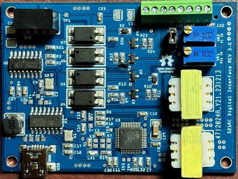
Circuit description:
The interface has only ONE Micro USB port which will connect to the computer. The circuit has the below main components:
USB Hub: SL2.1A Chip
USB Audio: CM108/CM108B chip
USB-TTL: CH340G chip
4 x 817 optocoupler for CAT/PTT/COS isolation
2x 600:600ohm Audio isolation transformer (Iron core)
CAT: RX and TX can be used for radio which use separate rx/tx for CAT control. For ICOM CIV, use the CIV jumper and take connection from either RX or TX.
COS: Sometime Carrier sense is needed when using the interface for Echolink or similar application, there are “COS” and “Inverted COS” available, chose which one to use as per the COS connection from the radio.
DC-DC power: The onboard 5V DC to 5V DC isolated power supply reduce the complexity of getting power from the RIG side.
Optional:
for CM108B: X3 and R7 is not needed, C5 and C6 need to be 10uF MLCC


Part List:
C5 C6 22pf [for CM108B replace with 106]
C3 C4 22pF
C26 10nF
C22 105
C17 C18 C23 C27 106
C21 C31 106 [Optional]
C29 107 MLCC
C13 C14 101
C11 104
C8 C32 105
C7 C10 C30 475
R17 R18 220R
R2 R3 R9 R12 R19 R20 R22 R24 510R
R8 1K5
R4 R10 R13 R14 R21 R23 10K
R11 33K
R16 47K
R7 1M [Not needed if CM108B]
L1 22uH
X1 X2 12MHZ
X3 12MHZ [not needed for CM108B]
D1 D2 1N4148WS
Q1 Q2 Q4 MMBT3904
Q3 MMBT5401
U4 U5 U6 U7 817
U2 CH340G
U3 CM108B
U1 SL2.1A
LD1 LD2 LED
USB MINI 5PTP
T1 T2 Audio isolation 600:600 transformer
VR1 VR2 10K multiturn pot
M1: B0505S 1W DC-DC isolation
J1: 8 pin 2.54mm PCB screw terminal
PCB Gerber [including part placement* and BOM]: DOWNLOAD
* Please check all parts orientation and values when using the CPL for PCBA
PINOUT:
8PIN Screw Terminal (Labels are corresponds to Radio/Rig side)
GND: Radio ground
OUT: Radio fix AF out (or audio from Speaker/Headphone)
IN: Radio fix AF in (or mic in)
TX: CAT TX Radio side (Computer side RX)
RX: CAT RX Radio side (Computer side TX) (*1)
PTT: Radio PTT pin (*2)
COS: pull up to activate COS/COR (*3)
COS (inverted): pull down to activate COS/COR
* 1: For ICOM CI-V short the RX and TX pin with the Header Jumper CIV. Connect CIV to any of these RX or TX terminal.
*2: Use DTR in the software for hardware PTT (if used CAT, PTT can be over CAT as well)
*3: Use CTS in the software for COS (not needed for HF radio digital mode can be used for Repeater controller, Echolink etc)
Schematic:

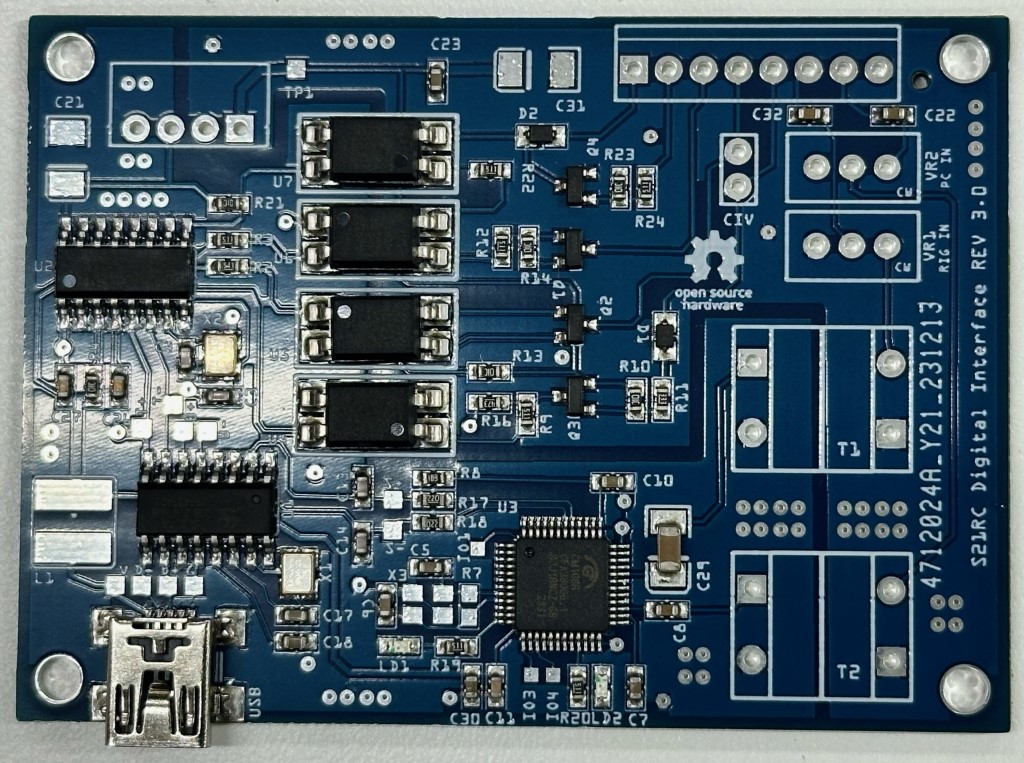
Above: PCBA (with SMD Components) without the through hole components.
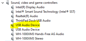
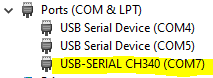
Settings:
Once the USB interface is connected – windows will automatically detect and install the Audio Codec (USB Audio Device), a Serial Port (please check from device manager the COM port number). Also HID for the CM108B will be installed which we are not using at this moment (you can experiment with HID if needed, the IO-1, IO-3 and IO-4 can be accessed on the PCB through the PADs exposed for such. Please remember that the IOs are not isolated.)

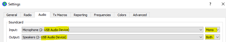
Example WSJTX settings shown below:
From the Audio TAB select the newly installed audio devices.
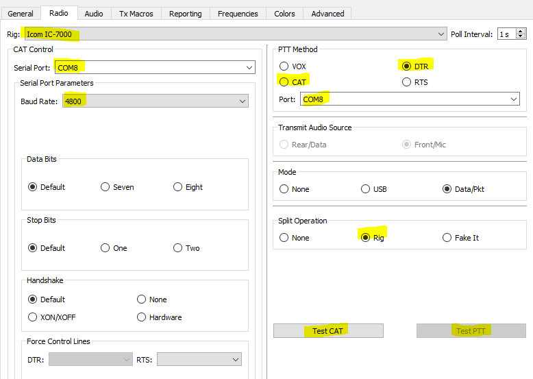
If you use CAT then select the Radio model from RIG dropdown (if you do not use CAT/Remote then select NONE), specify port and correct baud rate set in the radio. Click Test PTT – it should come green if test pass.
Select PTT method (if you use CAT/Remote then you can select CAT as PTT method). Chose DTR and select same Serial port number.
Split Operation select “RIG” only if you use CAT, this will automatically change your TX frequency when transmitting. If no CAT is used then select “None”.
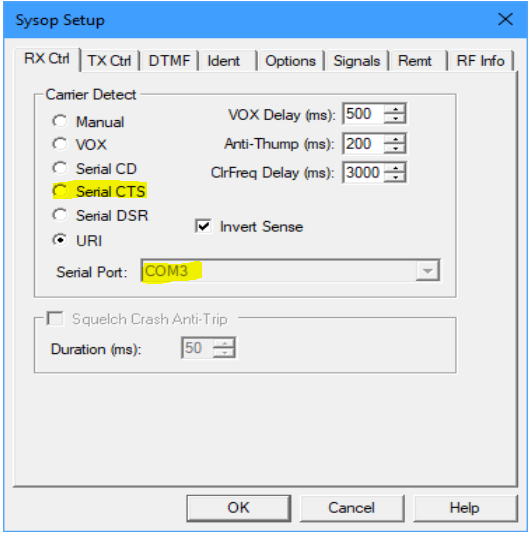
Example Echolink settings:
In the Sysop settings RX CTRL select “Serial CTS” and select correct Serial port from dropdown list.
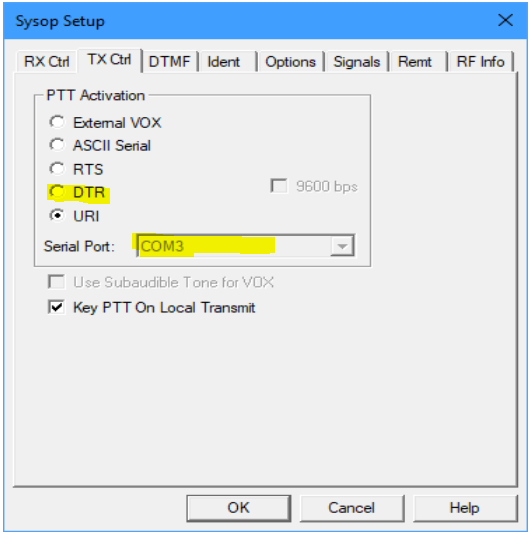
In the TX CTRL select “DTR” and select correct Serial port from dropdown list.
Trouble Shooting:
If you have RF return in the shack the USB cable might pickup RF and you may get disconnected or computer might show error. Using a USB cable with Ferrite Choke installed will eliminate this problem, or you can also put a Clamp on Ferrite on the cable at the computer ends.
For Local HAM in Bangladesh only:
I have few extra in hand. If you wish you can buy it.
Option 1 [1700/- BD Taka]: PCBA with SMD components soldered (without the Power inductor, Power isolation, 2x Transformer, 2x potentiometer and 8pin screw terminal.
Option 2 [2300/- BD Taka]: Fully assembled and tested, including the power isolation module, inductor, audio transformer, potentiometer and screw terminals soldered. Enclosure/Box and USB cable not included.
KEEP THE BALL ROLLING:
Apart from countless hours (and lots of coffee) to design the circuit, testing, coding thousands of line etc (In addition to my full time work) – I also had to order every component from of-shore for my experiment. As I do not sell KIT – there is no return except my own happiness.
If you like my work and wish to use it – you may show your appreciation and support my effort by a small donation. This is completely optional and has no effect on the support I try to provide over email/chat/Github. 73, S21RC
[paypal-donation purpose=”” reference=””]