Update:
13 November 2023:
Display firmware for Nextion 5 inch Intelligent (NX8048P050) uploaded.
4 August 2023:
Display firmware for Nextion 3.5 inch Basic (NX4832T035_011) uploaded [NOT RECOMENDED]
30 April 2023:
Display firmware for Nextion 3.5 inch Discovery (NX4832F035_011) uploaded [NOT RECOMENDED]
4 April 2023:
Display firmware for Nextion 7 inch Basic (NX8048T070) uploaded.
24 March 2023:
Display firmware for Nextion 7 inch Intelligent (NX8048P070) uploaded.
Display firmware for Nextion 5 inch Basic (NX8048T050) uploaded .
An Arduino Nano microcontroller based controller for my 600W HF LDMOS SSPA. This one is used with the DX-World protection board and SWR Bridge but any protection board with suitable signals should work:
From Hardware Protection board:
1. ID (current sense)
2. SWR error signal (optional)
3. High Power error signal (optional)
4. High Current error signal (optional)
From SWR Bridge:
Forward Voltage (Must be less than 50V)
Reflected Voltage (Must be less than 50V)
From Antenna Switch:
12V when PTT (BIAS LINE).
There are three main part:
1. Controller Board
2. Microcontroller Code
3. Display file.
V2.0 display has three page at this moment (More function will be added gradually – based on user feedback):
1. Main page
2. Setup page
3. Diagnostic page
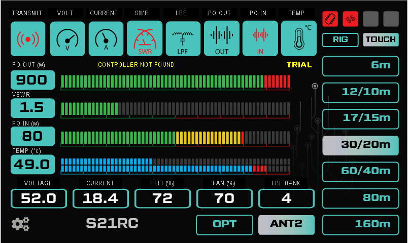
Main Page:
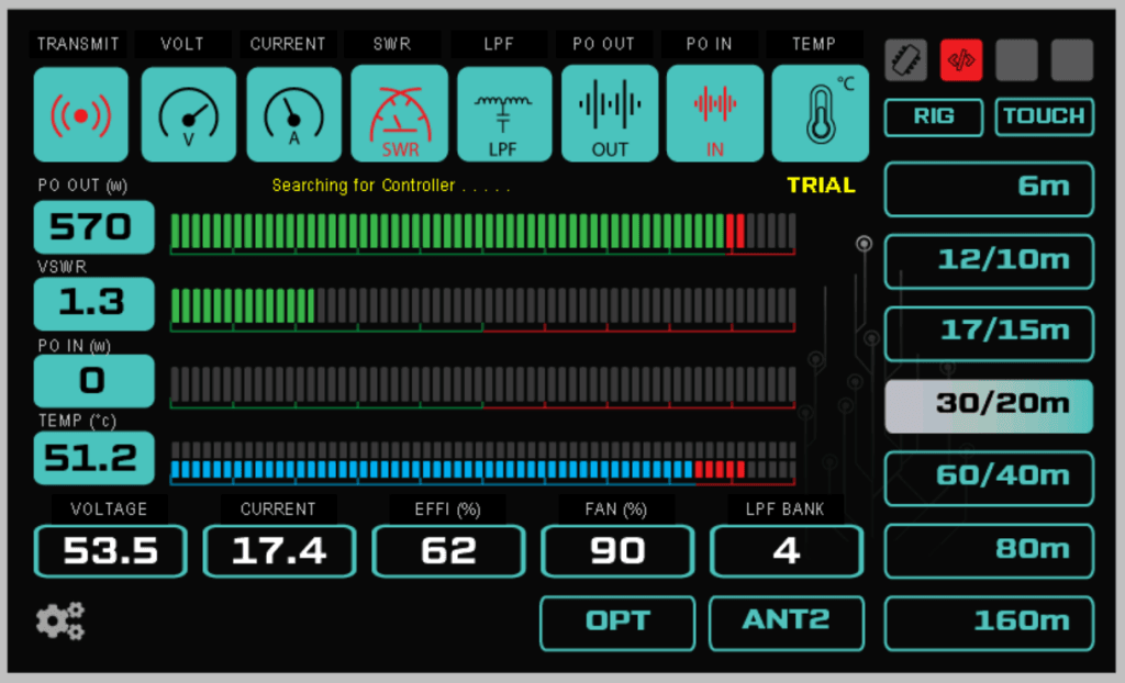
Above is the default power on page where we can see different parameters while operating the SSPA. The right side touch switches will be used for LPF band change when “RIG” button is not selected. The 8 position rotary band switch (optional) will have Touch + 7 band position – selecting any position apart from Touch will disable the touch band switches and select the band as per the rotary position – which will also show on the display.
Following features will not work with existing hardware (PCB V1.x) but will be available on Hardware Version 2.x which I am working on at this moment:
RIG: auto band selection from RIG (Band Voltage, BCD etc)
2nd Temperature: will available in future software update for V1.x and V2.x hardware.
PO IN: show power input from additional SWR bridge at input (I am out of SWR bridge so can not code yet)… for V2.x hardware.
PO in protection: for V2.x hardware.
Protection:
In addition to the hardware protection we have some software protection, this is just for a secondary safety measures and should not be relied on:
1. Temperature
2. High power out
3. High power in (in v2.x hardware)
4. High SWR
5. LPF mismatch (if Id is more than 10Amp and Po is less than 200W)
6. High current (Future software update)
7. High Voltage (future software update)
Setup Page
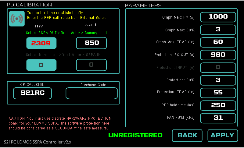
In setup page you can enter all the parameters and also perform the power calibration. Calibration is straight forward, press PTT and measure the power output from an external calibrated watt meter, enter the measured watt in the calibration box and press APPLY. that’s all – we are set.
You can also set your callsign here, please note this is a full featured shareware – the only change is the “TRIAL” status on the main display. if a valid registration code(please see registration portion below) is entered then the “TRIAL” text from main display and UNREGISTERED text from setup page will disappear.
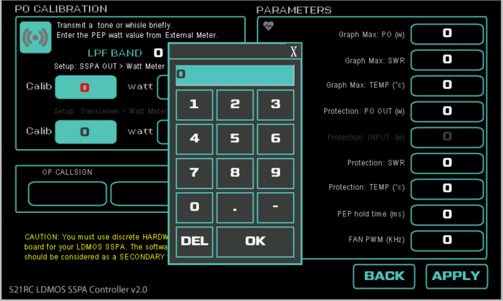
Unlike other menu driven system – entering data in the setup page is very user friendly due to the touch display- you use the onscreen keypad/keyboard to enter number/text.
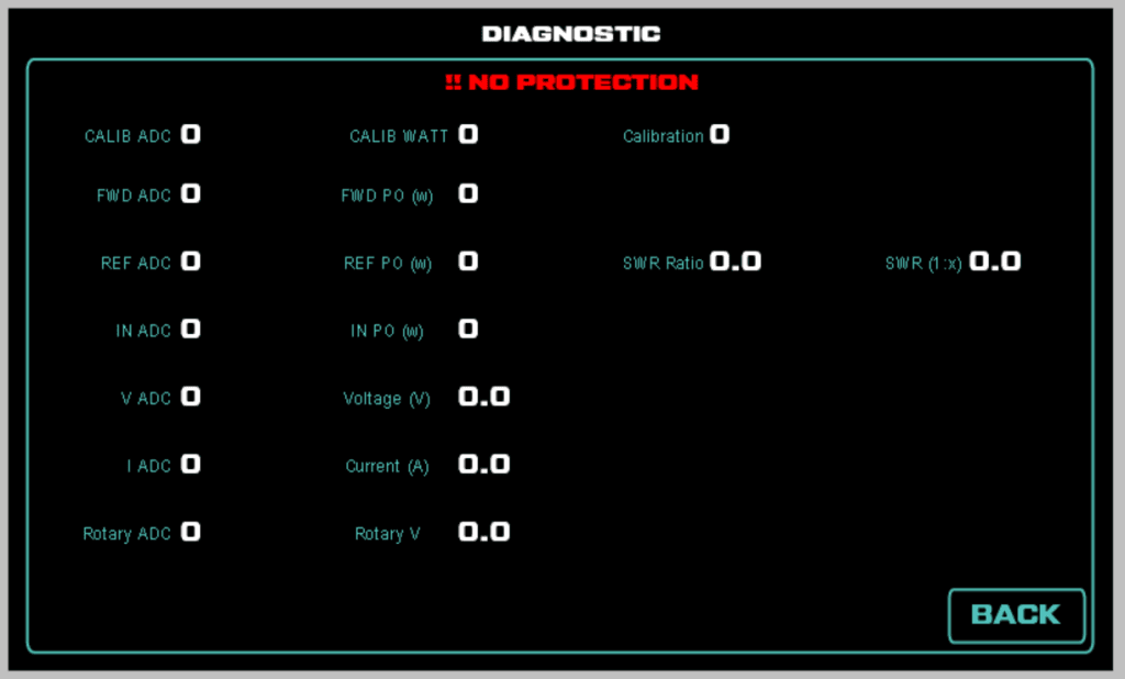
From the setup page we can access the Diagnostic page. BEAWARE: the software protections are not enabled for this page – this is intentional to see all raw parameters to debug. Make sure correct LPF is set on main page (or from rotary switch) before doing TX in this page.
Diagnostic page:
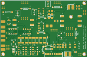
AA. DIY hardware board (V1.x): PCB Gerber, Parts list etc can be downloaded from here at GITHUB. The gerber can be sent to any PCB fabricator and usually cost 8-10$ for 5nos.
BB. Microcontroller Firmware: V2.0 Binary HEX files for Arduino Nano v3 DOWNLOAD (you need XLoader to write the hex file to the microcontroller).
CC. V2.0 Display Firmware for:
Nextion 5inch Enhanced HMI (NX8048K050): DOWNLOAD
Nextion 5inch Basic HMI (NX8048T050): DOWNLOAD
Nextion 5inch Intelligent HMI (NX8048P050) DOWNLOAD
Nextion 7inch intelligent HMI (NX8048P070): DOWNLOAD
Nextion 7inch Basic HMI (NX8048T070): DOWNLOAD
Nextion 3.5inch Discovery HMI (NX4832F035): DOWNLOAD
Nextion 3.5inch Discovery HMI (NX4832F035): DOWNLOAD
Download the ZIP file for your display model, extract the TFT file and copy on to the MicroSD card. Insert the card in the display and powerup. At first boot the firmware will be loaded. Once finished, power down the display and remove the card. ** Do not leave the card with the file in the display.
NOTE: I started this projects for my own LDMOS build. Some of the code routine I am using here also will be used in a commercial project and I am not in a liberty to open source it (please do not request for the C code or HMI files). You can use the full featured software as it is free of cost. I will try to provide some limited support as much I can manage (time wise).
Registration:
Apart from count less hours and lots of coffee for designing the circuit, testing, coding thousands of line etc (In addition to my full time work) – I also had to order each and every component from of-shore for my experiment.
[paypal-donation purpose=”” reference=””]
If you try the controller and like it – you may show your appreciation and recognize my effort by donating as little as 25$ (please drop me an email with your callsign for receiving the registration code). This is completely optional and has no effect on the support I try to provide.
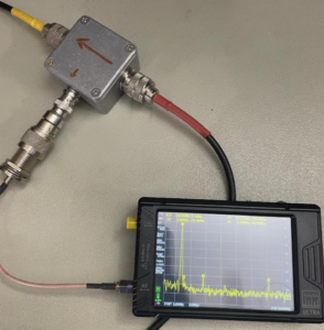
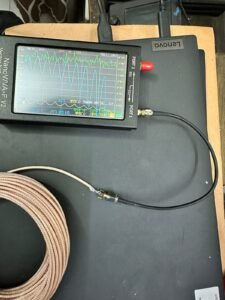
Glimpse of the controller during test:
salve , IT9CSD sta realizzando l’amplificatore con il controller 2v1. se ho ben capito serve un codice di slocco puoi farmi sapere come ottenerlo ?
grazie
p.s. e chiare che devo e faro una donazione
it9csd Salvatore
Could you include an HDMI file for the 4.3-inch Nextion on your website?
NX4827T043_011
I have access to two of these displays.
Thank you so much for the effort and time you put into this project.
Hi Marcelo, apology for seeing this comment late. 480×272 is too small to fit the display elements, sorry about it. You can try the lite version where all the codes are given and try to adjust for your display using nextion editor.
Amazing project! Congratulations! Couple of questions:
1) how can we back up the original file already there that came with the controller board, just in case…
2) any chance to change layout and colors?
3) if we don’t use the nextion lcd is it possible to have a window in the PC doing the same thing?
Hi Pedro, I am assuming you are referring the DXWorld-e controller. Please request them for the code or at least compiled hex. Their work is based on my code but I do not have their code or any idea what are the modification they did. As per license of my code any derivative or mod or project build based from my code should also come with same license, and they should make it open source. But we all know that is for a perfect world.
Hello Fazlay!
I bought a 5″ TFT display with its controller by DXWorld-e and I knew it is a reply of your ver 2.0 controller.
As it is ARDUINO based I wish to know if it is possible to remote control the amplifier with a PC connection/software via USB or Ethernet shield or even via the web.
Thank you!
Fabio, IT9GSF.
Hi Fabio,
that is based on my 2.1.Lite version code. the microcontroller has only one Serial/UART (which is already in use for Display) and not much I/O left. So it would be difficult to interface with a PC.
To solve all the shortcoming of this I designed Rev 3, which is open source and you can make your self if wanted.
Thanks,
73, s21rc
How to I calibrate power and swr my amplifier runs Abt 1 kw. I guess I got a bit confused..
Hi Joe,
with a dummy load TX in RTTY or FM mode while in the calibration page, enter the the value in the “watt” box and save,
https://www.youtube.com/watch?v=R-jvNjmwuWg see this video from 9:15 to 10:15 for more clarity (different version but same procedures). Thanks, 73, S21RC
Hello Fazlay,
Thank you very much for the great effort and time you put into this SSPA project.
I got v3.0 PCBs made locally here and ordered Nextion Intelligent NX1060P101-011C-I 10.1″.
is it possible for you to put a file for this Nextion on your homepage.
Hello Sasi, can you please confirm which version? Is it V2 (Nano) or V3 (Teensy)?
I am working on v3
Almost assembly of components is complete.
Few components are still in transit.
Thanks Sasi, will do the hmi over the weekend
How to I calibrate power and swr my amplifier runs Abt 1 kw. I guess I got a bit confused..
thank you sooo much I got it now you rock
Hello Fazlay,
I been trying to download the files but I just get “This page could not be found!”
Could you please look in to this?
I also sent an email, I’m ready to do a donation, but I can’t test anything yet without the files. Thanks.
Best regards,
VJV
Please try now. Recently I have moved the site from Bangladesh to a US datacenter, and the folder was not moved- now has been fixed.
73, s21rc
I downloaded your SSPA Controller V3 giver data from your website and requested it from JLCPCB, but an error was pointed out to me.
Message from JLCPCB
Hello,
Sorry to bother you, but we’d like to confirm with you an issue found when engineer making production file of your PCB order.
As shown below, there’s no outline layer in your file. Can we use the outer frame on silkscreen layer as the board outline? Is there any cut out, milling line on the board?
Your early reply will be highly appreciated, thank you so much!
How can I solve this problem?
Hi Hiroshi,
Could you please forward the email so I can see the image they sent. Thanks, Rabby
Hi Carlo,
I used a variable resistor instead of the switch and resistors to change bands.
I think it’s super cool that I have a smooth moving potentiometer to change the bands, Great Project.
Thanks
Pingback: S21RC SSPA Controller Hardware Rev 3.0.1 – S21RC Shack
Nice work Fazlay,
Is there any limitation on the forward value it can display if the Power Amplifier is rated at 2.5kwatt
The F and R voltage input has a voltage divider of 1:2, you just have to make sure that input doesn’t go above 10V (or 5v at the nano pins.). If voltage from your swr bridge is above 10v, you need to use an external voltage divider using two resistor (same ratio for Forward and reflected, no pot should be used)
at 2500 watt, the display at the left of the counter might show in two lines, upto 1999 it should works ok. This can be fixed with a smaller font, no problem.
I’ve built the board and have it on a 7” screen , band changing on screen switches the outputs fine , applying 12v to ppt input the screen comes up with restart SSPA to clear fault , same on all the inputs
Hi Paul,
The protection is triggering. Can you please set the parameters a bit high in the setup page and then try? Pls upload a Photo somewhere and share the link, of the screen (after PTT and error) so we can troubleshoot together. Also give me your setup detail: which protection board you are using etc.
Thanks, S21RC
hanks , the temp sensor isn’t reading so ordered more , would this cause the fault , the temp reading is = 50 c or something like that , I don’t have it connected to a amp , just bench testing board works as it should .
Feeding voltage into the inputs doesn’t make any of the swr , power etc move
Hi Paul,
Without the Amplifier and initial power calibration you wont see SWR/Power correctly. for 50C You can set the temp alert to 60 or more as a test. You can also go to the diagnose page and see the level. Many routines only actives once PTT is on (like SWR and PO), so you may need to feed PTT line 12V also.
Hi feeding 22v into ppt trigger the protection error straight away , the temp reading is negative 50 deg c , it’s not reading anything , sensor is no good .. will that trigger a protection error ?
I’ll wait for new sensors to arrive and do some more tests ..thanks for you’re reply’s
Hi Paul, yes, a negative temp reading will surely trigger the temp alert (if temp is not valid range – incase of faulty sensor – which is exactly the case now). Check the sensor separately with an Arduino if you have – sample code is with the dallas library. Please make sure the PCB modification is done – or else temp sensor will not work.
What modifications do I need to do ?
Hi Paul,
// NOTE: V1.1 PCB has a small mistake, please swap pin A6 and A5 on the PCB by cutting the trace and using small wire. As A6 can not be used as digital communication. Please see the Schematic in GIT to understand clearly.
Hello Fazlay
now it works my display is a Nextion 7 inch basic (NX8048P070-011)
thanks
73 Peter DH4JQ
Thanks , the temp sensor isn’t reading so ordered more , would this cause the fault .
Yes, if the sensor is faulty and the incorrect temp reading is above the trigger level. The code is for a DS1820 digital sensor, are you using that? There was a slight modification needed on the board – have you done that?
Hello Fazlay
is it possible for you to put a HDMI file for the Nextion 7 inch basic (NX8048P070-011) on your homepage.
Thank you very much for the much effort and time you put into this project.
have
73 Peter DH4JQ
Hi Peter,
NX8048P070-011 is 7 inch Intelligent series. Please confirm your model. if it is intelligent then the TFT file is already here to download.
The basic version is also uploaded just now, I do not have a basic so couldn’t test. But the simulator says all good.
Thanks again for the NX8048T050 compile… now i have a new rock in my way the heaven HI HI, Xloader wont start on my win 11, i open an issue on githut for it 😉
Nice and great job again Rabby
Nicolas VE2NNX
Hi Nicolas,
Xloader was the easiest way, there are other hex uploader as well. You can also try AVRDUDE (the uploader comes with and used by Arduino IDE), though it’s CLI.
avrdude -c arduino -P COM[x] -b 9600 -p atmega328p -D -U flash:w:objs/[filename].hex:i
where [x] is com port number the Nano is connected (can be found from device manager under ports), and [filename] is the HEX file name.
hi can i use the 3.5inch nexion display with your v2.0 firmware?
will it be the same graphics but smaller?
Hi George,
by default it will not work. The nextion display firmware is model specific.
fitting all this display component in the 3.5 would be very difficult due to the resolution. I will change the graphics and try to fit as much in a 3.5 for you (tell me the model number of your display), give me some time (next week I am out for camping). 73,
I
i have not buy the display yet but i noticed that after 3,5inches becomes very expensive,do you have to suggest where to buy a 5inch display for a good price?
thanks for your time and effort .
Hi George, I bought 3.5 and 5 inch from Aliexpress, seems 5 inch is around 60$ now a days at Ali.
yes ali i think is the lowest thanks again
hi faslay finally i got a 3.5” NX4832F035 for 40euros , the 5” was over 75euros including postage
could you please compile for me this display?
thanks in advance,best regards
73′ George.
Sure, I will make a smaller version for your NX4832F035. Just give me few days time. 73
no rush at all take your time anyway it will take at least 15-20days to receive it
thanks again
hi, i received the display today if you have the time could you please compile the code please? it is the NX4832F035_011
Hello George,
Please download and test it. 3.5 inch is too small to accommodate all component, so some fonts are small now.
Grazie
carlo iz2abz
thank you very much
HI,
I don’t have the 5 inch display but I have the 7 inch one model NX8048P070-011C-Y.
If possible, would you please send me the file to upload for my model.
Thank you
carlo iz2abz
Hi Carlo, as it is also 800×480 wont be a problem to create the firmware for that. Give me some time and I will compile for you. Thanks.
Nextion 7inch intelligent HMI (NX8048P070) uploaded, please check.