My TinySA has a max +6bdm input which is not enough to connect directly to the output of any RF PA unit. I also do not have any 50 or 60db RF attenuator with proper power rating to connect to the output of a SSPA. I searched the internet and found this (https://www.collinsradio.org/wp-content/uploads/2015/05/Build-a-Quality-RF-Power-Sampler-Jackson.pdf) by Don Jackson, W5QN which looks very easy to make.
I quickly searched for the components in my parts bin and found all of that, instead of T44-2 I have used a T50-2 core as that what I got. Resistors are 10R and 39R 1/4 watt 1% resistor. ordinary 5% would do as well.


The Secondary winding (pickup coil) is 32 turn of thin enameled copper wire on a T50-2 (Red color, Iron Powder) core. The primary winding is the RG142 coax where the shield will be connected to ground only at the IN port. Leave the shield floating for the OUT side.
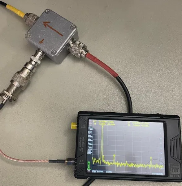
You must ensure that the unit is built in a metal box for proper shielding. Observe proper RF practice – keep the leads as short as possible. As stated in the original article, make sure the output portion is perpendicular to the main RF path.

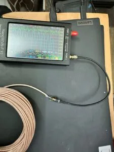
Having this sampler unit will be beneficial to observe the harmonics behavior, also I have a plan to test pure signal with HermesLite2 using this sampler – for that I have to make another same unit to see the result on SA.
I measured the +56dbm output of the PA and found around +5dbm at the SA, so around -51db at the sampling output.
** All the DIY projects here are just basic documentation of my own work which I made out of necessity/hobby. This is not a step by step tutorial – please do not ask for a youtube video, I assume that you have basic RF and Electronic knowledge. If you have any question fell free to put it in the comment section below and I will try to guide you as much possible. Thanks, 73, S21RC
